| |
 |
|
|
| |
| Commercial Kitchen Planning Kitchen
Piping |
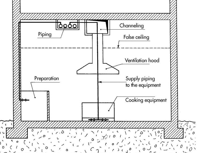
| |
The optimal position for supply piping is to use dorsal
piping attached by brackets to the top of a specific supply
conduit located beneath the kitchen (ideal for assembly,
inspection and maintenance).
|
| |
The piping leading
to wall mounted exit points must all go into chasing (conduits)
(except that for gas, which by law must always be in view).
Floor piping must be in special conduits in order to avoid
affecting the water-
proofing.
However, the structure of the building does not always
allow for this opti mal solution to be carried out and alternative
solutions have to be found.
The supply pipes in these cases can be placed in the ceiling,
separated from the kitchen by a false ceiling or in the
ceiling of the floor beneath the kitchen (generally in storerooms,
dispensers etc.) in view or with a false ceiling. They can
even be in the floor of the kitchen itself in a practical
trough which is aired and drained and from which the piping
to each 24 piece of equipment will extend in chasing.
Every appliance needing to be supplied with hot or cold
water, steam, or gas must be attached to the supply network
by means of conical joints pre ceded by a spherical valve
so that the supply can be cut off and a par ticular piece
of equipment disconnected from the system (for maintenance)
without having to stop other appliances functioning.
As already stated, it is not advisable to place the supply
network on view (above the plaster or the tiles) as this
would readily lend itself to becoming a dirt trap that is
difficult to clean. Only the gas system by law should be
on view for obvious reasons, however it’s piping is
painted and not insu lated. |
 |
Cold and hot water - The optimum hardness of water is between
5° and 7°F. The temperature of hot water can be between
48° and 60°C.
For the network, it is advisable to use normal galvanized
steel (UNI 3824) with special threaded galvanized joints and
connections. For the immedi ate use of hot water, the supply
network should have a re-circulation sys tem. |
Steam-condensation - Special equipment should
be adequately sup plied with the specific pressure required,
every appliance should have an appropriate steam condenser.
For the supply network it is normally advis able to use black
welded pipes, or black pipes of the type UNI 3824, with their
relative threaded joints and connections.
|
Gas - Equipment needing to be supplied by gas
has to adhere to current regulations. There are three types
of gas commercially available:
The systems used for the supply of gas have to comply to the
current regu lations for that type of gas. |
| |
| The supply network for cooking appliances and
dishwashers can be installed in an area below, adjacent or
in communication with those des
tined to the consumption of meals and/or the location of people
depen
dent on the following conditions:
1.The communicating door must be smoke resistant with
an automatic or
otherwise device to close the door properly in the event
of fire and an
appropriate smoke detector. 25
2. The area to contain the above system has to be provided
with one or
more ventilation zones with a surface of not less than 1/20th
of the area
of the kitchen with a minimum of 0.5 m .
3.The installation of cooking and dishwashing areas where
meals are to
be eaten is allowed provided that the whole area is constructed
bearing
in mind the previous two points.
4. Each burner must have a flame failure device with a
maximum gas cut
off time of 60 seconds if the flame is accidentally extinguished.
a) Fireproof and smoke proof poor automatically closed
by a smoke detector.
b) Smoke detector.
c) Fire proof and smoke proof door automatically closed
by a smoke detector.
d) Ventilation area.
e) Ventilation area.
f) Burners with flame failure devices.
g) Gas meter. |
| |
| |
| |
| Back
to Hvac App. Commercial Kitchen Main Page |
| Back to Hvac
Expert Main Page |
|
|
|
|
|
|
|
