| |
 |
|
|
| Kitchen Exhaust And Makeup Systems Design Procedure
|
| |
The Design Process
Successfully applying the fundamentals of commercial
kitchen ventila-
tion (CKV) during the design process requires a good
understanding of the loca
building code requirements, the menu and appliance preferences,
and the pro-
ject’s budget. Information about the kitchen equipment
and ventilation re-
quirements may evolve over the course of the design
phase. Data needed by
other members of the design team may require early estimates
of certain pa-
rameters (e.g., the amount of exhaust and makeup air,
motor horsepower, water
supply and wastewater flow rates). As more decisions
are made, new informa-
tion may allow (or require) refinements to the design
that affect exhaust and
makeup air requirements.
The fundamental steps in the design of a CKV system
are:
1. Establish location and “duty” classifications
of appliances including
menu effects. Determine (or coordinate with foodservice
consult-
ant) preferred appliance layout for optimum exhaust
ventilation.
2. Select hood type, style, and features.
3. Size exhaust airflow rate.
4. Select makeup air strategy; size airflow and layout
diffusers.
Steps 1 through 3 are discussed in this Design Guide;
Step 4 is the subject of
Design Guide 2, Improving Commercial Kitchen Ventilation
Performance – Optimizing
Makeup Air.
A good understanding of how building code requirements
apply to
kitchen design is essential. Local or state building
codes are usually based on
one of the “model” building codes promulgated
by national code organizations
(see sidebar). Our discussion of the building codes
will be limited to require-
ments that affect design exhaust and makeup air rates,
which are usually found
in the mechanical code portion of the overall building
code.
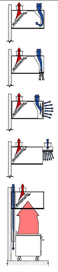
Historically, codes and test standards used “temperature”
ratings for
classifying cooking equipment. Although these temperature
ratings roughly cor-
related with the ventilation requirement of the appliances,
there were many gray
areas. During development of ASHRAE Standard 154, Ventilation
for Com-
mercial Cooking Appliances, it was recognized that plume
strength, which takes
into account plume volume and surge characteristics,
as well as plume tempera-
ture, would be a better measure for rating appliances
for application in building
codes. “Duty” ratings were created for the
majority of commercial cooking ap-
pliances under Standard 154, and these were recently
adopted by the International Mechanical Code (IMC)
|
|
|
. The Kitchen Ventilation chapter of the
ASHRAE Applications Handbook (2003 edition) applied
the same concept to
establish ranges of exhaust rates for listed hoods.
The appended Design Exam-
ples in this Guide reference duty classifications
for appliances. The duty classifi-
cations listed in the sidebar are from ASHRAE Standard
154-2003, Ventilation
for Commercial Cooking Operations.
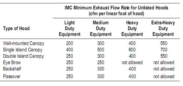
The IMC dictates exhaust rates based on hood type
and appliance duty.
Table 1 states these exhaust rates in “cfm per
linear foot of hood” (“linear foot”
in this case applies to the distance from edge to
edge along the front face of the
hood). The Code requires that the exhaust rate for
the highest duty-rated appli-
ance be applied to the entire hood. The Uniform Mechanical
Code (UMC), used
in many California jurisdictions, requires calculating
exhaust rates based on
square-footage of capture area (capture area is the
open area defined by the
lower edges of the hood). The UMC uses temperature
classifications for appli-
ances, as described above. Both the IMC and the UMC
require a minimum 6-
inch hood overhang (front and sides) for canopy style
hoods. |
| |
 |
Kitchen
Exhaust And Makeup Systems Design Procedure 2 |
| Commercial
Kitchen Exhaust and Makeup Air Systems Design |
. |
| Back to Hvac Applications
Main Page |
| Back to Hvac Expert Main
Page |
|
|
|
|
|
|
|