|
FREEZE PROTECTION DESIGN PROCEDURE
1. TEMPERATURE DIFFERENTIAL
Determine the temperature differential to be
maintained by subtracting the ambient temperature
from the fluid temperature to be maintained. (TF -TA).
Typically, for pipe freeze protection applications, the
pipe temperature should be maintained at 40°F. Pipe
temperatures should be maintained at 110°F for clog
prevention of grease disposal lines and 40°F for viscosity
maintenance of fuel oil lines.
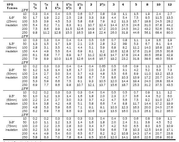
2. HEAT LOSS
Use Table 1 to look up the heat loss associated with
the pipe diameter and thickness of insulation. If a rigid
insulation such as calcium silicate is used, the pipe
heat loss should be increased to that associated with the
next larger size. Insulation should also be oversized when
using any cable other than the standard self-regulating
HSR, without overjacket. This will compensate for the
space of the heating cable. As an example, you would
use 2-inch pipe diameter heat losses for 11/2 inch pipe
heating application if rigid insulation were used. Heat
loss figures from Table 1 include a 10% safety factor.
Another Table
3. ADJUSTMENTS TO HEAT LOSS VALUES
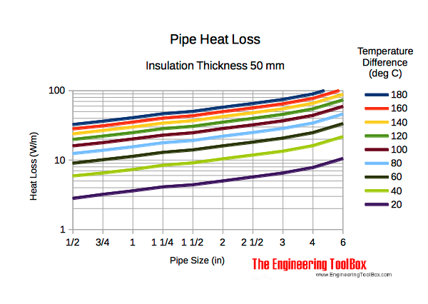
The heat losses in Table 1 are based on glass fiber
insulation. If other insulations are used, multiply the
heat loss value by the correction factor (shown in
Table 2) for your insulation.
Heat losses are based on outdoor applications with 20
mph wind. If piping is used indoors, multiply heat loss
values by 0.9.
4. DETERMINE CABLE P0WER
Using heat loss determined above, select appropriate cable from
Performance and Rating Data chart. For heat loss in excess of
20 W/ft, use multiple cables. For example, for heat loss of 23
W/ft, use two 12 W/ft cables. Cable power may exceed heat loss
by up to 50%. It is also possible to spiral cable on pipe such
that the power applied to the pipe exactly matches the pipe heat
loss. For example, for heat loss of 13 W/ft, a 10 W/ft cable can
be spiraled on the pipe such that 1.3 feet of cable are wound
on every foot of pipe, resulting in exactly 13 W/ft being applied
to the pipe. However, spiraling requires significant extra labor
to install and significant clearance around the pipe.
EXAMPLE
|