Cryogenic liquid nitrogen systems/oxygen plants are available
in size from 50 m³/hr (70 liter/hour) to 500 cum/hr
(700 liters/hour) capacity. It is safe and efficient to
operate and the oxygen confirms to North American and European
Pharmacopia and standards. The output of LIQUID OXYGEN can
be stored in a liquid oxygen tank. Liquid Nitrogen can be
available as a by product simultaneously upto 99.999% (PPM
GRADE) purity. The plant is extremely versatile and all
the possible product variants are possible you can either
take 100% Liquid oxygen out put or 50% Liquid oxygen output
directly into cylinders or 50% Liquid oxygen and 50% Liquid
nitrogen.
Manufacturing Process :
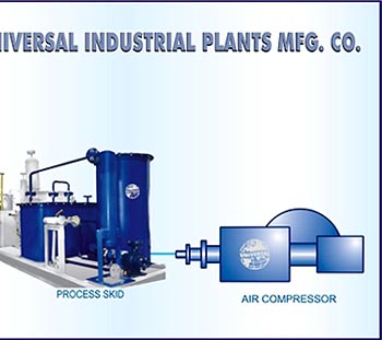
1. Compression Of Atmospheric Air By Air Compressor
In order to consume the free saturated air, an efficient
dry-type suction filter is used to suck it from atmosphere
into the first stage of the horizontal balanced opposed,
lubricated reciprocating air compressor. This compressed
air is then chilled to 12°C in a chilling unit at a
temperature of 12 degree centigrade to a moisture separator.
Prior to its entry into the Molecular Sieve Battery, the
condensed moisture is first removed & in order to make
air oil free, it is passed through an OIL ABSORBER before
this is sent to MOLECULAR SIEVE BATTERY.
2. Purification of Air By Process Skid
Consisting of twin towers, the Molecular Silver Battery
operates the packed Molecular Sieves. When chilled air passes
through this particular tower, it helps in removing the
moisture and Carbon dioxide present in the air. When one
of the towers gets regenerated by passing waste Nitrogen
gas at 200°C through a reactivation heater, then the
other tower is under production which gets exhausted and
regenerated by similar process after a gap of 8 to 10 hrs
before use. The vicious cycle continues. Before entering
the AIR SEPARATION COLUMN, the dust particles gets filtered
in the DUST FILTER.
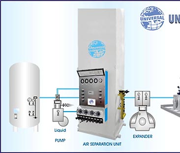
3. Cooling of Air By Expansion Engine (Expander)
The air should be cooled in the air separation unit to temperatures
sub-zero (cryogenic) before the liquefication process. After
this procedure, its main portion skid enters the expansion
engine through the heat exchanger no. I where the air temperature
drops to around -165°C by the Expander, which is sophisticatedly
designed with Teflon piston rings assorted with hydraulic
mechanism with leak proof ball valves.
4. Separation If Liquid Air Into Oxygen And Nitrogen By
Air Separation Column
The cold gained from outgoing waste nitrogen & oxygen
is used for cooling the chilled, oil free and moisture free
air at (-80)°C . This enters into multi-pass HEAT EXCHANGER
NO.I while a part of it even enters a multi-pass HEAT EXCHANGER
NO. II or LIQUIFIER constructed of special Alloy tubes.
The air cools to (-170)°C & prior to its entry into
the bottom column & is further cooled, liquefied due
to joule Thompson Effect before making its way through an
expansion valve. Known as the rich liquid, it later enters
into feed tray of top column in the bottom column. While
in the top column, POOR LIQUID, a form of liquid nitrogen
makes its entry as a reflux. It takes away the latest heat
of condensing Oxygen and gets vaporised & on the other
hand the liquid Oxygen flows down the trays of the top column
into the Condenser passes through a Sub-Cooler to a LO Pump.
5. Compression and withdrawal of liquid and gaseous oxygen
for storing in storage tank and cylinder filling
|